Location: 04-112
Coordinator: Dr. Payam Nayeri
Description
The Cal Poly EE Department operates the Electromagnetic Compatibility (EMC) Laboratory (UHF band) for student projects and pre-qualification EMC characterization including radiated and conducted emissions, and radiated susceptibility and immunity testing.
All electronic equipment must meet EMC standards, including the above mentioned measurements, prior to product release to the general public. These tests must be performed by a certified laboratory; however, multiple test sessions while developing potential shielding solutions may be cost-prohibitive. The Cal Poly EMC chamber offers local companies an alternative to certified-chamber testing while developing EMC shielding solutions for their products and involving EE students in solution development and testing.
Fee-For-Services Testing
The ElectroMagnetic Compatibility (EMC) Laboratory is available for Fee-For-Services radiated and conducted emissions, and immunity and susceptibility testing. Past projects include:
- Enerpro, Inc. (Goleta, CA) carried out Radiated Susceptibility testing in the Cal Poly EMC (ElectroMagnetic Compatibility) Chamber Laboratory. Enerpro, Inc. also provided funding to route three-phase power to the EMC chamber to facilitate susceptibility testing.

- Crystal Engineering (San Luis Obispo, CA) completed radiated immunity testing in Cal Poly’s EMC Chamber on a pressure sensor system, model APM030C.
 EMC (ElectroMagnetic Compatibility) Emissions Chamber Development
EMC emissions chamber development and construction [1-3] includes:
- Extension of external copper mesh frame: 14’L × 9’W × 7.5’H to 16’L × 9’W × 9’H
- Design and construction of internal 2” × 4” support structure (for ferrite tiles)
- Installation of 0.5” plywood – 26AWG sheet metal – 0.5” plywood mounting surface for ferrite tiles
- Ferrite tile (4” × 4” × 0.25” thick) installation: 6006 tiles
- Connector panel door: allows cable entry through chamber wall
- Chamber door design: tile design around main entry
- Turntable and motor specification
- Probe antenna specification and acquisition
- Spectrum analyzer, software-controlled, specification and acquisition
To accommodate test articles with maximum dimensions 18” L × 18” W × 6” H, the chamber was extended in length by 4ft and in height by 1ft: see Fig. 1 below [4].
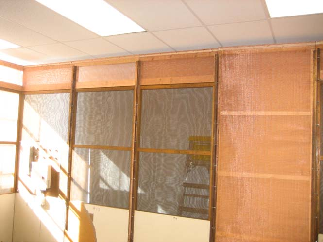
Fig. 1: EMC Screen Room Expansion: Note new panel on right, 1ft height extension panels
RF (radio frequency) isolation was characterized to determine attenuation levels from outside to inside the newly-renovated chamber: see Fig. 2 below.
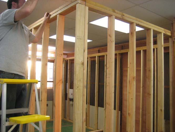
Fig. 2: Ferrite Tile Support Structure inside EMC Screen Room
Worst-case measured isolation is 19dB at 1GHz, while the best-case is 64dB at 100MHz. Between these frequency limits, the average attenuation is approximately 30dB. Since commercial chambers have minimum isolation levels of 90dB to 100dB, additional measures to increase isolation will be employed including the installation of fingerstock to the door jamb (both sides) and patching holes in the copper mesh. Sheet steel between plywood layers should also improve isolation.
To support the plywood sandwich structure mounted on the ceiling, vertically placed 2” × 6” boards were installed across the double-stacked 2” × 4” top layer: see Fig. 3 below.
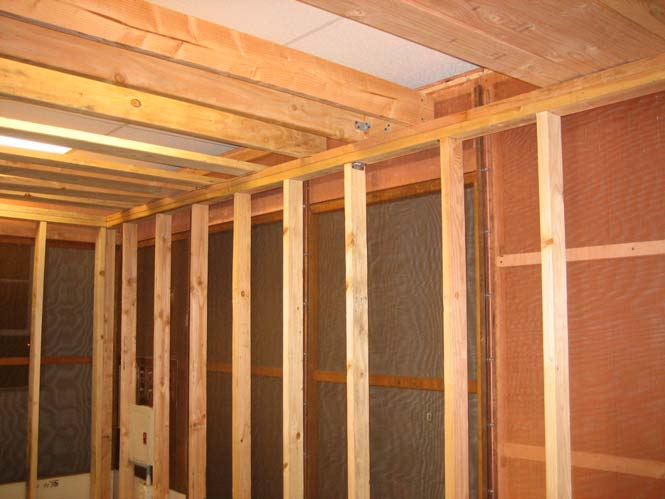
Fig. 3: Ferrite Tile Support Structure inside EMC Screen Room: 2” × 6” Ceiling Joists
In conjunction with the screen room expansion, a wooden support structure was developed to accommodate a plywood structure (plywood - sheet metal - plywood) upon which ferrite tiles will be mounted: Fig. 4 below. The layered structure consists of two ½ inch thick plywood sheets attached to either side of a 26AWG steel sheet mounted onto the support frame.
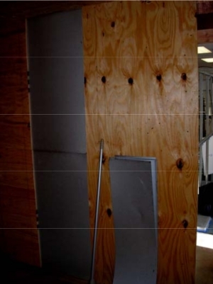
Fig. 4: Plywood – Sheet Metal – Plywood (1⁄2 inch thick) Sandwich Structure
With the mounting structure in place, ferrite tiles (4” × 4” × ¼” thick each) are attached to the structure with zinc-coated steel screws: See Fig. 5 below
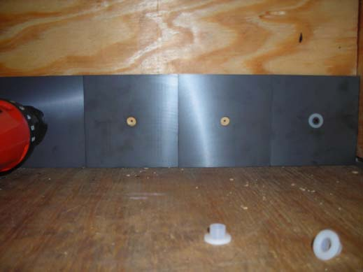
Fig. 5: Ferrite Tile Installation
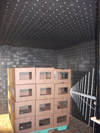
Through C3RP/ONR support, a total of 6,006 ferrite tiles (143 boxes, 42 tiles/box) [4, p. 107] were purchased from Samwha Corporation, in addition to 6,006 plastic inserts and mounting hardware. Chamber construction is shown below (Fig. 6 below).
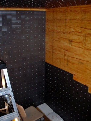
Fig. 6: Ferrite Tile Installation; Ceiling, Back, and Side Wall
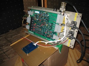
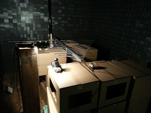
A turntable, stepper motor, and angular position control system was designed and implemented inside the new chamber to enable radiated emissions measurements as a function of angular direction from the equipment under test (EUT). A cardboard cutout indicating the size of the proposed turntable and required location on the chamber floor is shown in Fig. 7 below.
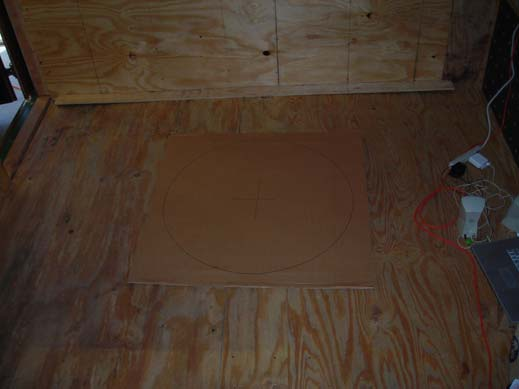
Fig. 7: Turntable Size and Location Relative to Front Wall
Since the motor is located outside the chamber, two holes for the belt drive were established through the screen room wall, and plywood-sheet metal and ferrite tile layers. Techniques to minimize isolation impact and tile absorption performance was examined and the optimum method or combination employed.
The chamber has undergone characterization testing to compare radiated emissions performance against pre-compliance requirements, including isolation.
References:
- ANSI C63.4-2003: Methods of Measurement of Radio-Noise Emissions from Low-Voltage Electrical and Electronic Equipment in the Range of 9 kHz to 40 GHz, American National Standards Institute.
- CISPR 22: Information technology equipment, radio disturbance characteristics, limits and methods of measurement, Comité International Special des Perturbations Radioélectriques.
- FCC, Part 15 (Radio Frequency Devices): Subpart A: General, Subpart B: Unintentional Radiators, Subpart C: Intentional Radiators
- M.I. Montrose, E.M. Nakauchi, Testing for EMC Compliance, Approaches and Techniques, Wiley & Sons, 2004
